Setting the Scene: Why EV Validation Needs a Rethink
Bold fact: the most expensive bug in an electric car is the one that hides inside the pack. In ev testing, the lab never sleeps. A validation team runs charge–discharge cycles through the night, while ev battery testing equipment streams gigabytes of measurements—cell voltages, pack current, and thermal gradients—into a data lake. A single pack can see thousands of cycles before sign-off. Yet small gaps in sampling or fixture control can turn a week of results into noise. That’s the scenario. The data footprint is huge, the decision window is tight, and the stakes are real.

So here’s the question: are your benches capturing the right signals at the right fidelity, or just generating dashboards? Modern rigs must align with BMS behavior, CAN bus timing, and power converters under transients. Edge computing nodes now sit near the cyclers to shrink latency and improve sync, but alignment still fails when procedures are brittle. We need rigs that adapt to the profile, not force the profile to fit the rig (because the vehicle won’t). This is a comparative moment for our industry. The labs that shift from static test scripts to adaptive workflows cut churn and raise confidence. Let’s move into the friction points and see what’s actually breaking the loop.
The Hidden Cost of Legacy Rigs and Static Protocols
Where do legacy rigs fail?
Technical view: traditional benches look solid on paper, but underneath they miss context. Static profiles assume linear behavior; cells do not. Legacy cyclers often sample slowly during fast events, so you lose resolution during DC fast charge steps and pulse power sweeps. Fixture heat soak masks drift, and calibration schedules slip. Data loggers trigger asynchronously, so pack current, cell voltage, and chamber temperature fall out of phase by seconds—an eternity in transient analysis. That is how misalignment creeps into SOC/SOH estimation and into downstream BMS tuning.
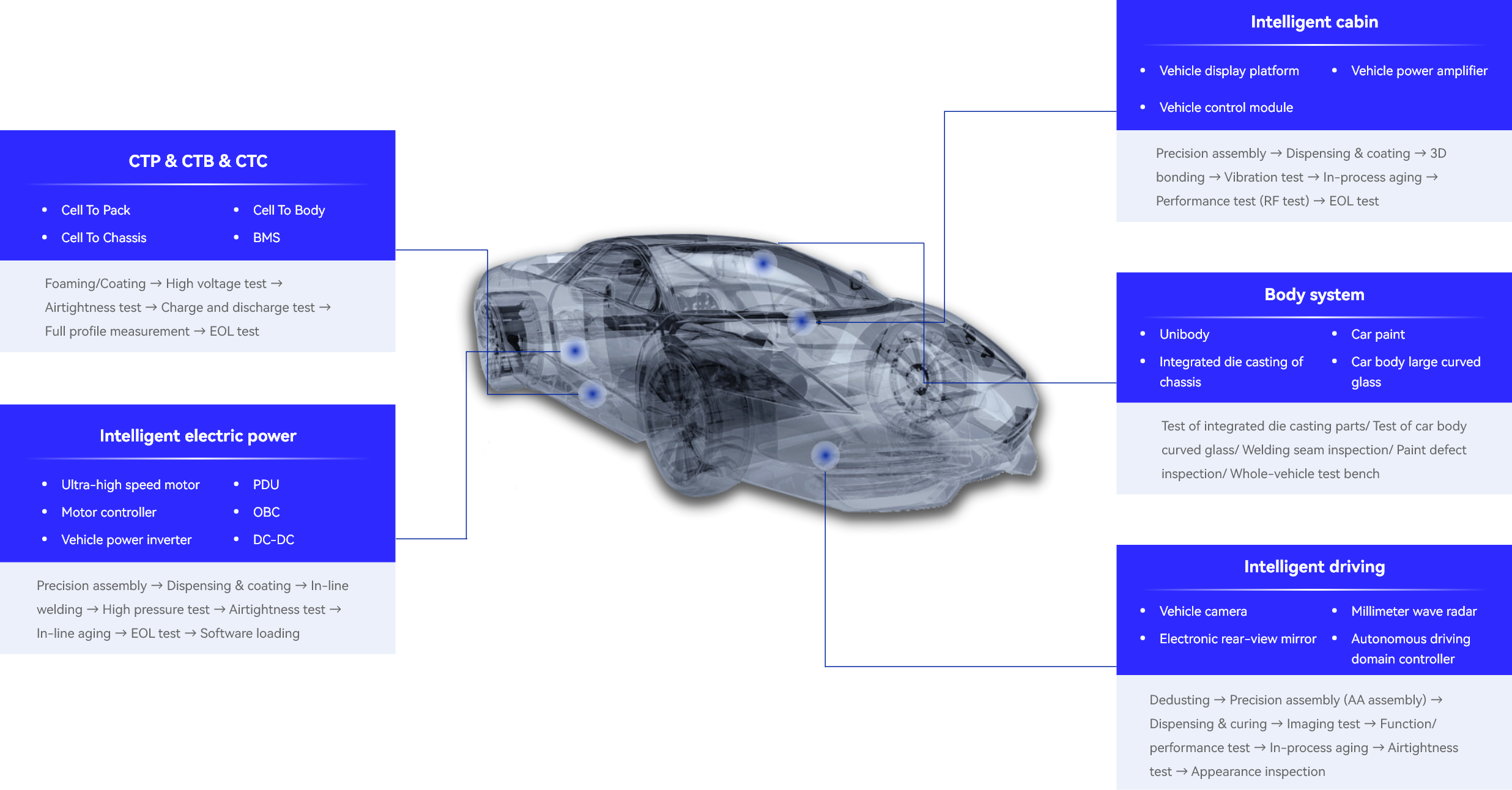
Look, it’s simpler than you think. When procedures drive the lab instead of responses, you end up with brittle runs. Manual recovery after a fault injects bias. EIS measurements captured on a different day than cycle life data? Apples and oranges. Without synchronized fault injection and repeatable ramp rates, you cannot test thermal runaway barriers under realistic loads. And the hidden pain points keep stacking up: unreliable harnesses, noisy shunts, and script debt that no one wants to touch. Teams then chase anomalies that are really wiring artifacts—funny how that works, right? The result is a gap between “pass on the bench” and “field behavior” under regen spikes, inverter ripple, and charger handshake errors. This is why modern labs are moving to synchronized controllers, hardware-in-the-loop triggers, and tight timing across cyclers, chambers, and BMS emulators.
Comparative Leap: Principles Behind Adaptive, Future-Proof Labs
What’s Next
Semi-formal take: the next wave blends control theory with pragmatic lab ops. Instead of one-size-fits-all charge tables, rigs implement closed-loop profiles. They watch impedance rise, heat flux, and voltage sag, then adjust steps in real time. New control stacks integrate chamber PID, cell balancers, and power converters under a single scheduler. That keeps timestamps aligned and reduces drift when currents swing. Add edge analytics for on-the-fly anomaly flags—micro-ohm changes in DCIR, subtle hysteresis shifts—and you get early warnings before a full failure mode. This is not sci-fi; it is standard practice in high-throughput labs adopting unified timing buses and deterministic triggers.
Let’s compare. Old flow: script → run → export → post-process → argue. New flow: intent → adaptive run → inline features → verdicts. The difference is reaction speed and traceability. With synchronized clocks and deterministic sampling, CAN frames, thermal camera pixels, and pack current share the same time base. Now a regen spike from the inverter correlates to a micro-rise in cell temperature at 50 ms resolution—actionable, not anecdotal. Inline models (Kalman filters, simple observers) track SOC/SOH drift while the sequence runs. If a cell crosses a stress threshold, the rig modulates C-rate to map the boundary, not blow past it. You can tie this to your existing stack of ev battery testing equipment and keep your lab floor intact. And yes, better data means fewer reruns—cost drops follow.
Future outlook? Expect more hardware-in-the-loop with charger emulation, vehicle ECU shadowing, and automated fault trees. Expect cyclers that speak the same clock as your chamber and your BMS emulator. Expect integrated safety controllers that fast-trip before thermal runaway while recording high-rate snapshots. The comparative win is clear: fewer blind spots, faster root cause, cleaner handoff to design. That shortens validation sprints and reduces warranty risk without inflating headcount. And one more thing—distributed edge nodes will pre-filter noise so your cloud doesn’t drown in raw samples. Small change, big effect.
How to Choose: Three Metrics That Keep You Honest
Advisory close, same tone: First, timing integrity. Demand a single, verifiable clock across cycler, chamber, BMS emulator, and sensors; aim for sub-10 ms sync under load. Second, adaptive control depth. Check whether profiles can react to impedance, temperature, and voltage limits in real time—not just abort—with documented safety envelopes. Third, traceable data lineage. Insist on deterministic sampling, lossless metadata, and built-in calibration audits so every verdict is reproducible. Use these metrics to score options side by side, and you’ll spot the real maturity fast. Keep it practical, keep it measurable—and keep the lab honest. For teams seeking a reference point or deeper detail, you can also review established solution providers like LEAD.